Galvanic Isolation: Creating a "New Source"
The main advantage of an ABL Transfo isolation transformer lies in the galvanic isolation between the primary and secondary windings. Physically, there is no electrical connection between the input and the output. Energy is transferred solely by magnetic field.
This means that the transformer’s secondary is considered a new, autonomous power source.
The "Blank Slate" of Potential
At the output of an isolation transformer (if no terminal is earthed), the potential is floating. By default, you are in an IT system. It is up to the installer to decide which SLT they want to create on the secondary, regardless of the system present on the primary.
Technical note: A transformer can be supplied by a primary network in a TT system and deliver a TN-S or IT system on the secondary. It is this flexibility that makes the transformer a network architecture tool.
Use Case: Creating an IT System for Continuity of Service
This is the prime application for industries where production downtime is costly (or dangerous).
The Principle
To establish a local IT system (islanding), an isolation transformer is used whose secondary neutral point is not connected to earth (or is connected via a high impedance).
The Role of the Transformer
It contains the fault. If a phase touches the frame on the machine powered by the secondary:
- The fault current is negligible (a few mA), as there is no return path to earth on the secondary.
- No protection device trips. The machine continues to run.
- Galvanic isolation prevents the fault from propagating upstream and disturbing the primary network.
Essential Equipment: The IMD
Warning, "not tripping" does not mean "ignoring". The standard requires the installation of an Insulation Monitoring Device (IMD) on the transformer’s secondary. It signals the first fault so that a maintenance team can intervene before a second fault occurs (which would cause a trip).
ABL’s Expertise: For these applications, we recommend transformers with reinforced insulation and, often, an electrostatic screen to minimise capacitive disturbances.
Use Case: Switching from TN-C to TN-S (Combating Disturbances)
In many older industrial installations, the TN-C system (combined Earth and Neutral in the PEN conductor) is ubiquitous.
Problem: Unbalanced currents and harmonics flow through the building’s metal structures via the PEN conductor. This severely disrupts sensitive electronics, PLCs, and IT equipment.
The Transformer Solution
Inserting an isolation transformer (preferably with a Dyn11 winding connection) allows you to:
- Stop the propagation of the PEN conductor: The PEN stops at the primary.
- Recreate a clean neutral: On the secondary, the neutral point is connected to earth locally. This creates a "clean" TN-S (Separate Earth and Neutral) system.
The transformer here acts as a firewall against common-mode disturbances and stray currents from the upstream network.
To ensure the safety of your SLT, the transformer sizing must be rigorous. Here are the key points our ABL engineers monitor:
A. Winding Connection (Vector Group)
To create a stable earthing system on the secondary, the winding connection is critical.
- Dyn11 (Delta on primary / Star on secondary): This is the recommended standard.
- The star connection on the secondary makes the neutral available and easy to earth (for creating TN-S or TT systems).
- The delta connection on the primary blocks 3rd order (and multiple) harmonics and balances the loads.
B. The Electrostatic Screen
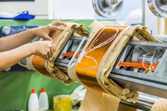
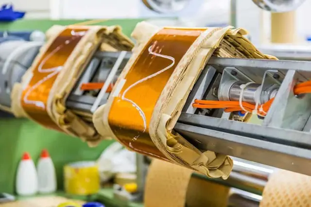
This is a copper foil inserted between the primary and secondary windings, connected to earth.
- Function 1: Safety. In the event of insulation failure, it prevents the high voltage from the primary from passing to the secondary.
- Function 2: EMC Filtering. It significantly reduces capacitive coupling, filtering out high-frequency noise from the grid. Essential for powering server racks or instrumentation.
C. Protection Against Inrush Currents
A high-performance isolation transformer often has a significant inrush current upon energisation (up to 25x In). If you are creating a critical SLT, you cannot afford nuisance tripping at start-up.
Advice: Use type D or K circuit breakers on the primary, or ask ABL for "low inrush current" transformers (specific magnetic core design).
Why Choose ABL Transfo for Your SLT Architectures?
A transformer intended to manage an earthing system is not a standard catalogue product. It is a safety component.
At ABL Transfo, we manufacture dry-type solutions (single-phase or three-phase) specifically adapted to these constraints:
- Custom-made: Option to integrate the electrostatic screen as standard.
- Compliance: Strict adherence to IEC 61558-2-4 standards (Isolating transformers).
- Adaptability: We can bring out the neutral point to a specific terminal block or provide ±5% adjustment tappings to compensate for voltage drops and ensure the stability of your new earthing system.
In Summary
The isolation transformer is much more than a voltage converter. It is the cornerstone that allows you to:
1. Isolate your installation from upstream network faults.
2. Change the earthing system to adapt safety to the application (TT, TN-S, IT).
3. Filter disturbances to protect electronics.
Do you have a project requiring a specific earthing system?
(Hospital, Data Centre, Industry 4.0)
Don’t take risks with your equipment specifications. Contact our design office to validate the technical choice (Winding Connection, Power, Protection Index).
Contact the Design Office