
Practical guides

Isolation transformer for boilers: the complete guide

An isolation transformer for boilers gives the boiler a clean neutral and, with its tappings, brings a high supply back to about 230 V. How it works, which VA rating to choose, how to wire the single N-PE link and which mistakes to avoid.

  • Bureau d’études
  • 8 min read

This article is also available in français, Deutsch, español and italiano.

Contents · 8 sections
  1. What is an isolation transformer for a boiler?
  2. The two main problems and how to fix them
  3. Choosing the right boiler isolation transformer
  4. Frequently asked questions
  5. Schematic and typical wiring (230 → 230 V)
  6. Common mistakes with a boiler isolation transformer
  7. FAQ – isolation transformer for boilers
  8. When an isolation transformer for a boiler is the right answer

A 230/230 V isolation transformer for boilers electrically isolates your boiler from the public supply.
The result: a clean neutral, less interference and far fewer lockouts.

Problem 1: residual voltage on the neutral → the boiler locks out.
Solution: an isolation transformer with a new neutral created on the secondary side (a neutral-to-earth link, N-PE, at a single point).

Problem 2: supply voltage too high (e.g. 245 V) → the boiler, designed for 230 V, may drop out and lock out.
Solution: a 230/230 V boiler isolation transformer with tappings (−5%/−10%) or a 240 V primary, to bring the output back to about 230 V. In practice: get the power rating (VA) right, choose an IP rating suited to the plant room and keep the protection in order (RCD, earthing).

Isolation Transformer 230V – 230V

Price range: €56.90 through €2,219.90 including VAT
Select options This product has multiple variants. The options may be chosen on the product page
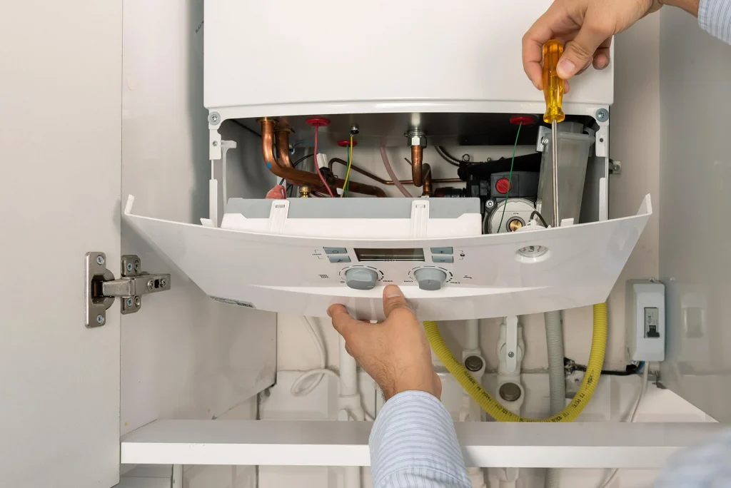
Isolation transformer for a boiler

What is an isolation transformer for a boiler?

A simple definition

A 230/230 V isolation transformer for a boiler provides galvanic separation between the mains circuit and the boiler circuit. The primary (the incoming 230 V) and the secondary (the supply to the boiler) are not electrically connected: energy passes from one to the other by magnetic coupling alone.

That is what makes it possible to recreate a clean neutral on the boiler side: the secondary neutral is referenced to earth (a single N’-PE link), which steadies the differential measurement and removes phantom voltages.

What it solves (and what it does not do)

  • ✔️ Residual voltages on the neutral: generally eliminated by the single N’-PE reference; the boiler finally sees a clear 0 V.
  • ✔️ Common-mode interference (capacitive coupling, long cable runs): greatly attenuated.
  • ❌ Automatic voltage regulation: an isolation transformer does not regulate. To correct a supply that runs high (e.g. 245 V), you use the tappings or a model with a suitable primary (240 V) so that the output is about 230 V.

Isolation transformer vs autotransformer vs voltage regulator (AVR)

  • 230 V / 230 V isolation transformer: galvanic isolation plus a clean neutral. It is the first choice for boilers prone to neutral faults and interference.
  • Autotransformer: changes the voltage (240 → 230 V step-down) without isolation; useful if the voltage level is the only problem.
  • AVR (voltage regulator): keeps the voltage steady when the supply varies widely; it can be combined with an isolation transformer for the best result.

The two main problems and how to fix them

Problem 1: residual voltage on the neutral → lockout

Typical symptoms: the boiler shows intermittent fault codes, locks out for no apparent reason or trips the RCD. A multimeter sometimes shows a small N-PE voltage (a few volts), the sign of a “dirty” neutral.

Why does it happen? In real installations, small stray capacitances (long cable runs, appliances connected in parallel, insulation faults elsewhere) create floating voltages. The boiler’s control board is very sensitive: it misreads this unstable neutral and drops out.

The robust fix: install a 230/230 V boiler isolation transformer and create a clean neutral on the secondary side by linking N’ to PE at a single point. This re-references the boiler’s 0 V, removes the residual voltages and steadies the measurement. Nine times out of ten, that settles it.

Problem 2: supply voltage too high (e.g. 245 V) → lockout

Some areas receive a supply of around 240–245 V.

If the boiler only tolerates 220–240 V, it may protect itself (shutdown, fault code) or even age prematurely. Two approaches work well:

Choose an isolation transformer with tappings (e.g. −5% or −10% on the primary). This lowers the actual voltage seen by the secondary and brings it back close to 230 V.

Opt for a 240 → 230 V isolation transformer if the difference is permanent. A good habit: measure off load, then on load, and adjust the tapping to aim for about 230 V at the boiler.

Choosing the right boiler isolation transformer

Step 1 – Work out the power rating (VA)

Careful: the “24/30/35 kW” figure for your gas boiler is its heat output, not its electrical power. The electrical supply mainly feeds the electronics, the igniter, the fan and the pump or pumps. In most cases the load is nowhere near a kilowatt.

Gas boiler (domestic): typical consumption < 300 W. With a margin of ×1.5 to ×2, a 300–500 VA transformer is often suitable.

Electric boiler: here the electrical load really is heavy (kW). Size for the actual load, add a margin (start-up, cos φ) and move up to ratings of ≥ 1 kVA if necessary.

Rule of thumb: VA ≈ (W / cos φ) × (1.2 to 1.5)
If you do not know the cos φ, take 0.8 to be on the safe side.

Quick examples:

  • 100 W → 160–200 VA
  • 250 W → 400–500 VA
  • 800 W → about 1 kVA

Step 2 – Voltage and tappings

The starting point is 230/230 V. If your supply runs high, choose either a 240 V primary (output ≈ 230 V) or a multi-tap primary (0/−5%/−10%) for fine adjustment.

Step 3 – Environment and mechanical design

Type: toroidal (compact, very quiet) or EI core in an IP23 IK08 enclosure for plant rooms (sturdier mechanical protection).

Ambient temperature and thermal class: provide adequate ventilation and avoid spaces that are too confined.

Connection: clearly marked terminals, suitable cable glands, standard fixing centres and overall dimensions that fit the space available.

Step 4 – Compliance and protection

Choose compliant transformers (e.g. EN 61558), as our transformers at ABL Transfo are. On the installation side, follow the wiring regulations that apply in your country (NF C 15-100 in France). Provide suitable RCD protection (often a 30 mA Type A device on the secondary side, depending on the arrangement), time-delay fuses or circuit breakers of the correct rating, and sound earth (PE) continuity.

Key point: a single N’-PE link on the secondary to create the neutral reference. Not two, and not “wherever it happens to be convenient”: one point, and one only.

Frequently asked questions

►  What does a boiler isolation transformer do?
It protects the boiler against mains disturbances (overvoltages, harmonics, leakage currents) and galvanically isolates the installation to prevent electrolytic corrosion in the water circuits.
►  What size should a boiler isolation transformer be?
Most domestic boilers draw 100 to 400 VA. A 230 V / 230 V transformer rated from 500 VA to 1 kVA is sufficient. For an industrial boiler, refer to the manufacturer’s specifications.
►  Is an isolation transformer for boilers compulsory?
As a general rule it is not compulsory, but it is strongly recommended where there are mains disturbances or in at-risk locations (lightning, damp environments). Some installation standards make it mandatory.

Schematic and typical wiring (230 → 230 V)

Where to fit it in the circuit

The boiler isolation transformer is fitted upstream of the boiler, after the main protective device in the consumer unit. Ideally it sits as close to the boiler as possible, to keep the cable runs on the secondary side short (better immunity).

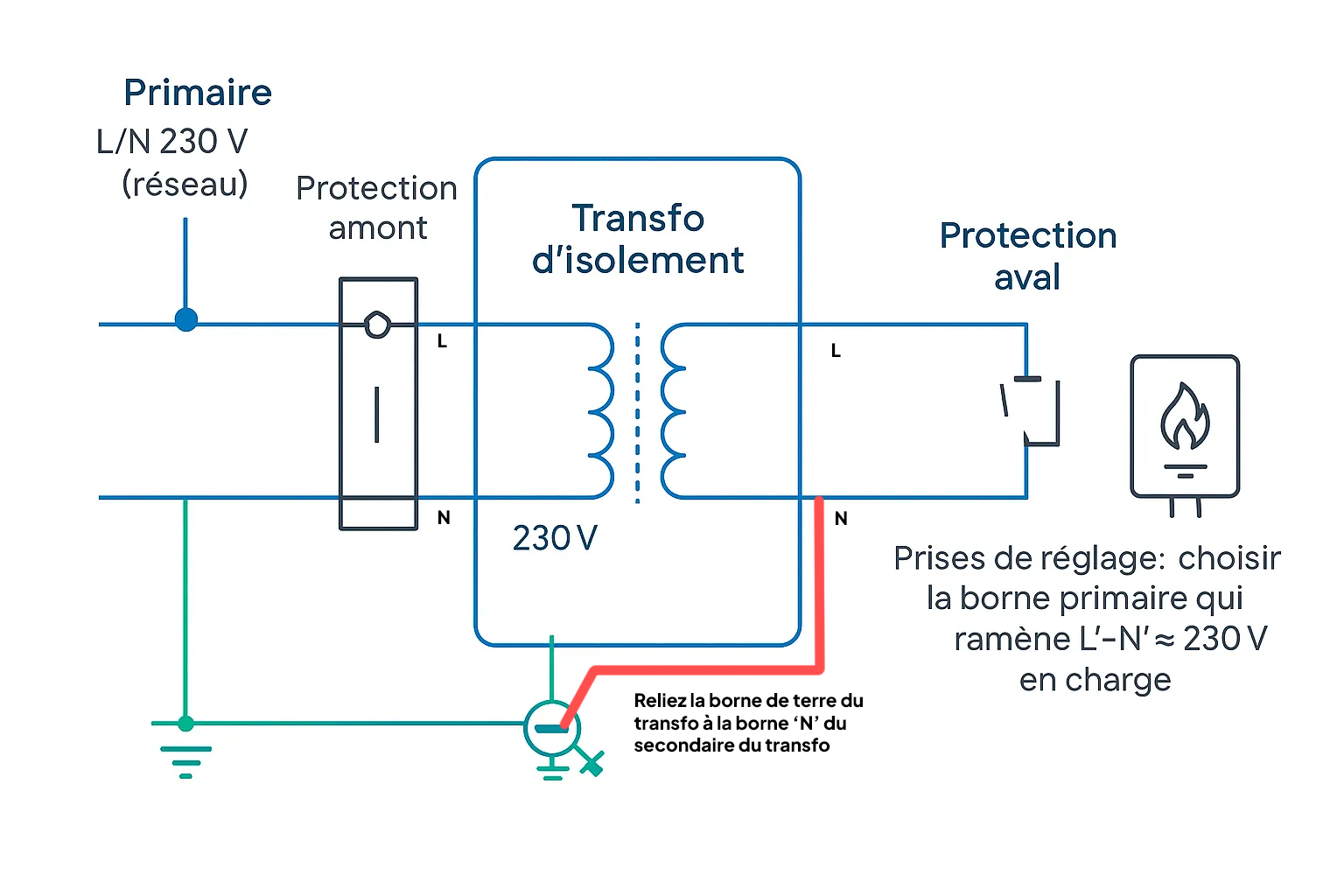
Functional diagram


Wiring diagram of an isolation transformer for a boiler

Wiring diagram of an isolation transformer for a boiler

Primary: L/N 230 V (mains) → upstream protection → transformer primary (230 V terminal, or −5/−10% tapping as required). Secondary: L’/N’ 230 V → downstream protection → boiler supply terminals. Earth: PE carried straight through for the exposed metalwork, plus a single N’-PE link on the secondary to create the clean neutral. Tappings: choose the primary terminal that brings L’-N’ back to ≈ 230 V on load.

Safety note

Isolate the supply before any work and prove dead. Make one N’-PE link only. Multiplying the reference points creates loops and brings the faults back. Before connecting the boiler, measure L’-N’ (about 230 V) and N’-PE (about 0 V), and check the polarity of the conductors.

Common mistakes with a boiler isolation transformer

  • Confusing heat output (kW) with electrical power (W): you risk oversizing for no good reason (cost, bulk).
  • Forgetting the N’-PE link on the secondary: you lose the benefit of the clean neutral and the faults come back.
  • Multiplying the earth reference points: no loops.
  • Choosing an autotransformer when the priority is isolation: the boiler will go on seeing an unstable neutral.
  • Undersizing the transformer (VA too low): overheating, voltage drop, premature ageing.
  • Ignoring the actual local voltage (measure it!) and forgetting the tappings.

FAQ – isolation transformer for boilers

Does a boiler isolation transformer stabilise the voltage?

Not on its own. It isolates and lets you create a clean neutral. To correct 245 V, use the tappings or a 240 V primary, or even an AVR if the supply varies a great deal.

Why connect the secondary neutral to earth?

To set a stable 0 V reference and remove the residual voltages that upset the boiler. A single N’-PE link, in the right place.

What rating (VA) should the isolation transformer have for a gas boiler?

In most cases 300–500 VA is enough (electronics + pump). Check the boiler’s rating plate, estimate the consumption and add a margin of 20–50%.

Autotransformer or isolation transformer?

If you have neutral faults or interference, choose the boiler isolation transformer. The autotransformer merely changes the voltage, without isolation: useful only when the voltage level is the sole problem.

Does it comply with the standards?

Yes, provided you choose compliant ABL Transfo models (e.g. EN 61558) and the installation follows the wiring regulations that apply in your country (NF C 15-100 in France). If in doubt, have it checked by a qualified electrician.

When an isolation transformer for a boiler is the right answer

If your boiler drops out because of a “dirty” neutral or a supply measured at 245 V, a correctly sized 230/230 V boiler isolation transformer, with tappings and a single N’-PE link, settles the vast majority of cases. You gain in stability, in safety and in the service life of the electronics. Need advice straight away? Contact ABL Transfo: we go through your measurements and point you towards the right rating (VA), the tapping to use and the enclosure best suited to your premises. Careful manufacture, expert support.

A question about this article?

Your email address will not be published. Required fields are marked *

Your question is published once it has been approved.


Design office

A question about your installation?

Tell us about your supply and your equipment: we’ll recommend the right transformer, standard or custom-made, and reply within 48 hours.

+33 4 66 80 14 33Monday to Friday, 8 am – 6 pm (French time)