
How to Test a Transformer: The Multimeter Method
How to test a transformer when a gate, 12 V spotlights or pool lighting stop working? Five multimeter checks, the normal readings measured on our own units, a virtual multimeter for your diagnosis, and how to order the right replacement.
- Bureau d’études
- 19 min read
This article is also available in français, Deutsch, español and italiano.
Contents · 13 sections
- How to test a transformer: the five-measurement method
- Before you start: power off or power on?
- Measurements 1 and 2: winding continuity
- Measurement 3: insulation between windings and to frame
- Measurements 4 and 5: no-load voltage and on-load voltage
- The symptoms that speak before the multimeter
- Testing a transformer for spotlights, garden, pool or gate
- Electronic transformers and power supplies: a different method
- Toroidal and three-phase transformers: the special cases
- Repair or replace: how to decide
- Reading the plate to order the right replacement
- Frequently asked questions
- Your diagnosis in five steps
Knowing how to test a transformer saves a lot of pointless purchases. When a gate will not open, 12 V spotlights stay dark or the pool light refuses to come on, the transformer is often blamed wrongly. Five multimeter checks are enough to settle it.
This guide takes them in order, from the safest to the most telling, with the readings we take on our own units, wound in Gailhan, in the south of France. A virtual multimeter helps you interpret your reading, and the last part shows how to read the rating plate to order the right replacement.
Key points
How to test a transformer with a multimeter?
With the power off, measure the resistance of the primary, then of the secondary: a finite value proves the wire is not broken. Then check the insulation between windings and to the frame. With the power on, measure the no-load voltage, then the on-load voltage, and compare them with the plate.
A transformer reads higher than its rating off load: is that normal?
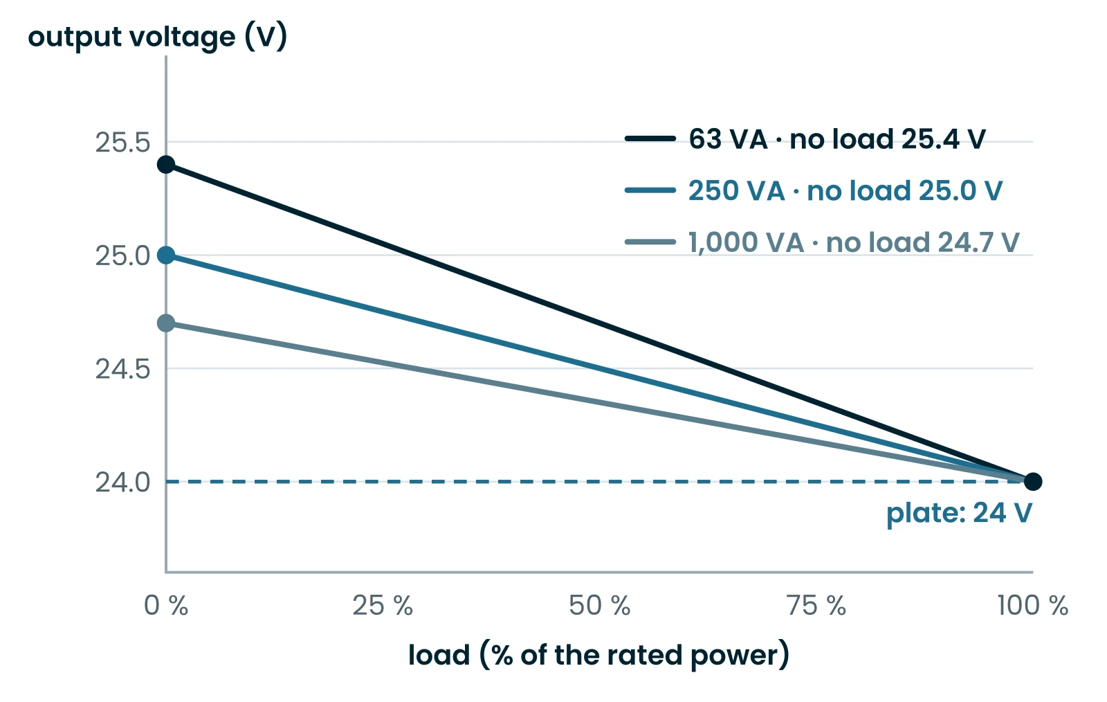
Yes. A transformer is designed to give its rated voltage at full load. Off load it gives a little more: 25.4 V on our 230 V / 24 V 63 VA, 24.7 V on the 1,000 VA. A no-load voltage 3 to 6% above the plate is therefore normal.
What can a multimeter not see?
A few shorted turns: the primary resistance drops by only a fraction of a percent, invisible to an ohmmeter. An insulation fault that only shows at high voltage, too. These faults give themselves away differently: heat off load, low voltage, a smell of hot varnish.
When should the transformer be replaced?
When a winding is open, when an insulation fault appears, or when it heats up and loses its no-load voltage. On small ratings, replacing costs less than rewinding. Note the plate: voltages, power and dimensions are enough to find the equivalent.
How to test a transformer: the five-measurement method
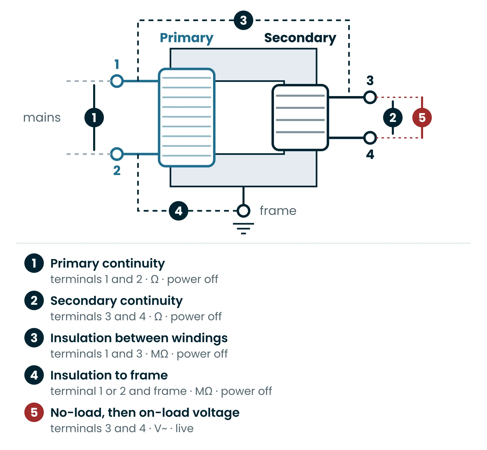
A transformer is simple: two coils of insulated wire wound on a stack of steel laminations, with no moving parts. It can only fail in three ways: a broken wire, turns touching each other, or insulation that lets current through to the other coil or to the frame.
Each measurement targets one of these faults. The first four are done with the power off, on the ohms range; the fifth with the power on, on the volts range. If you want to know how to test a transformer without missing anything, follow this order: the safest first, the most telling next.

- Primary continuity, terminals 1 and 2, power off.
- Secondary continuity, terminals 3 and 4, power off.
- Insulation between primary and secondary, terminals 1 and 3.
- Insulation to frame, between a terminal and the laminations.
- No-load voltage, then on-load voltage, at terminals 3 and 4, power on.
The virtual multimeter below shows how to test a transformer step by step. Pick a test: the probes move to the right terminals and the display shows what you should read. Then enter your own reading: the tool tells you whether the unit is sound, open, shorted or poorly insulated.
Virtual multimeter
Pick a test: the probes move to the right terminals and the display shows the expected order of magnitude. Then enter your own reading to get a diagnosis.
What you should read
≈ 13 Ω
from 5.3 Ω to 33 Ω
Where to put the probes
Terminals 1 and 2, unit unplugged, Ω range.
Diagnosis
Enter your reading, or tick OL.
The expected values come from our design software for single-phase units with a 230 V primary. Another manufacturer winds differently: to test a transformer of another make, keep the order of magnitude, not the decimal.
Before you start: power off or power on?
Testing a transformer always starts with the power off. In Great Britain, the Health and Safety Executive sets out how to work on or near electrical equipment in its guide Electricity at work: safe working practices (HSG85).
- Power off: pull the plug, or switch off the circuit breaker and make sure nobody else can switch it back on. Then check with the multimeter, on a volts range, that no voltage is present.
- Disconnect one wire from each winding: otherwise the ohmmeter also measures the circuit board or the lamps connected to it.
- Power on: only for voltage readings, probes held behind their finger guards, never touching a primary terminal.
A transformer housed in a consumer unit, a gate control box or a pool plant room sits next to 230 V terminals. If you are not comfortable, ask a qualified electrician: for them it is a matter of minutes.
Measurements 1 and 2: winding continuity
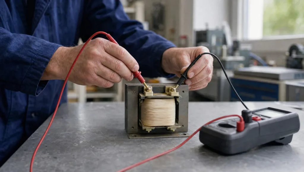
Any serious answer to the question of how to test a transformer starts here. A digital multimeter is all you need. Set it to its lowest ohms (Ω) range. Touch the two probes together: the display shows the resistance of the leads, often a few tenths of an ohm. Note it, then measure between terminals 1 and 2, then between 3 and 4.
- A finite value: the wire is continuous from end to end.
- OL, or a “1” on the left of the display: the resistance is above the range, the circuit is open. The winding is broken, or an internal thermal cut-out has opened.
Why the primary reads much higher than the secondary
The resistance of a wire rises with its length and falls with its cross-section. The primary of a 230 V / 24 V unit has about ten times more turns than the secondary, in a wire with about a tenth of the cross-section. The two effects multiply: the primary reads around a hundred times more than the secondary.
On our 230 V / 24 V 63 VA, the design gives 691 turns on the primary and 77 on the secondary. The resistances follow: 20.6 Ω on one side, 0.27 Ω on the other. The more powerful the transformer, the thicker its wires and the lower its resistances.
| Rating | 230 V primary | 24 V secondary | No-load voltage | Drop at full load |
|---|---|---|---|---|
| 63 VA | 20.6 Ω | 0.27 Ω | 25.4 V | 5.5% |
| 100 VA | 13.3 Ω | 0.16 Ω | 25.4 V | 5.3% |
| 250 VA | 4.3 Ω | 0.05 Ω | 25.0 V | 4.1% |
| 1,000 VA | 0.73 Ω | 0.01 Ω | 24.7 V | 2.9% |
For a 12 V secondary, the resistance falls by roughly another factor of four: half the turns, in a wire with twice the cross-section. Your multimeter will then show almost the same value as its leads alone. That is not a short circuit: it is normal.
What continuity does not prove
A correct value only says that the wire is not broken. If two or three primary turns touch because their enamel has burnt, the resistance drops by less than 1% over 691 turns: no multimeter will see it. Yet those shorted turns form a closed loop that heats up as soon as the power is on.
That is why it is never enough to test a transformer with an ohmmeter alone. Knowing how to test a transformer means running all five checks; the off-load voltage, and a careful touch after ten minutes with nothing connected, say far more.
Measurement 3: insulation between windings and to frame
A conventional transformer separates the primary from the secondary: no wire links them, which is galvanic isolation. On the multimeter’s highest range, often 20 or 40 MΩ, measure between a primary terminal and a secondary terminal, then between each winding and the frame: a fixing screw or a scraped lamination.
- OL everywhere: no hard fault.
- Any value, even several megohms: one winding touches the other or the core. Do not power the unit again.
The limit is real when you test a transformer with everyday tools: the multimeter measures with its own battery, at a few volts. Cracked insulation can hold at 3 V and break down at 230 V. An electrician’s insulation tester applies 500 V DC and settles it. In our workshop we go much further before every dispatch: our 230 V single-phase units withstand 3,000 V for 60 seconds between primary and frame, and 3,500 V between primary and secondary. That is their dielectric strength.
One exception before testing a transformer of this type: on an autotransformer, primary and secondary share the same winding. Continuity between them is normal; only the insulation to frame can be tested.
Measurements 4 and 5: no-load voltage and on-load voltage
This is the most telling step of testing a transformer. Reconnect it and set the multimeter to AC volts (V~). First measure the mains voltage at the primary, then the secondary voltage at terminals 3 and 4 with nothing connected: that is the no-load voltage. Finally reconnect the appliance, switch it on and measure again: that is the on-load voltage.
Why the no-load voltage is above the plate
When current flows through the windings, their resistance costs a few volts. The manufacturer compensates by adding a few turns to the secondary, so that the voltage is right at full load. Off load, those extra turns show: the voltage is above the plate.
The smaller the transformer, the larger the gap. On our 230 V / 12 V, the no-load voltage reaches 12.7 V at 63 VA and 12.4 V at 1,000 VA. On our 230 V / 230 V 1,000 VA, it reaches 236.6 V. Reading 12.7 V on a transformer marked 12 V is therefore the sign of a healthy unit. Anyone learning how to test a transformer should keep that figure in mind.

The mains makes the output vary
The output follows the mains, in the turns ratio. And 230 V is not a fixed value: the IEC 60038 standard sets the nominal voltage of European networks at 230 V and 400 V, and they are held within ±10% of that value. A 240 V supply gives 4% more at the output; at 220 V, 4% less. An off-load reading that looks high may simply reflect your supply.
Move the sliders below to see the output voltage change with load and mains voltage, on five of our models.
Output voltage versus load
Move the sliders: the output voltage falls as the current rises, and follows the mains voltage. Values from our single-phase range.
Output voltage
12.7 V
Output current
0.00 A
Deviation from plate
+5.8 %
At 0 % load, on 230 V mains, this 230 V / 12 V · 63 VA gives 12.7 V for 12 V on the plate. Off load it gives 12.7 V: that is by design, not a fault.
Interpreting your two readings
| What you measure | What it means | What to do |
|---|---|---|
| Off load: plate + 3 to 6% | Healthy unit | Look for the fault downstream: cable, board, lamp. |
| Off load: 0 V, mains present | Open winding or thermal cut-out tripped | Replace the transformer. |
| Off load: 15% or more below the plate | Shorted turns likely, especially if it heats off load | Replace the transformer. |
| On load: plate − 5% or better | Load correctly sized | Nothing to do. |
| On load: drop far larger than off load | Overload, cable too long or too thin | Check the power drawn and the cable size. |
An excessive drop on load often comes from the cable, especially at 12 V where the current is high. Our page on 230 V to 12 V transformers lists the output current of each rating, the figure you need to size the cable for the distance.
The symptoms that speak before the multimeter
Even before you reach for the meter, the transformer often gives clues: learning how to test a transformer also means learning to observe it. Look, listen, smell, then touch carefully with the power off.
Hot off load
Warm is normal: its no-load losses heat it a little. Too hot to touch with nothing connected, it has shorted turns.
Noise
A steady hum is normal. A buzz that grows louder points to an overload or loose laminations.
Smell
A smell of hot varnish or burning means the insulation has overheated. Do not put it back into service.
Fuse
A fuse that blows at every switch-on: a short circuit in the transformer, or in the appliance it feeds.
For a blown fuse, disconnect the secondary and switch on again: if the fuse holds, the fault is downstream, in the cable or the appliance. If it still blows with nothing connected, the transformer itself is shorted, and there is little point in testing a transformer any further.
Thermal protection: a transformer that comes back by itself
Many small transformers, for doorbells, gates or lighting, hide a thermal protection inside their winding: a thermal fuse, which cuts out for good, or a bimetallic strip, which resets as it cools. An appliance that stops after twenty minutes and starts again an hour later often has a bimetal at work: it is protecting the transformer from an overload.
In that case the transformer is not at fault: the load is too heavy, or the ventilation too poor. An open thermal fuse, on the other hand, reads on the ohmmeter like an open primary: OL between terminals 1 and 2.
Testing a transformer for spotlights, garden, pool or gate
The method stays the same, but every installation has its traps. Here is how to test a transformer in the four cases we come across most often.
Spotlights and garden lighting
First weigh the unit in your hand. A laminated-core transformer of 60 VA already weighs more than a kilo; an electronic transformer of the same power fits in your palm and weighs a few tens of grams. The second is tested differently: see the next section.
To test a transformer with a laminated core, measure the no-load voltage: 12.4 to 12.7 V for a 12 V unit, depending on its rating. Then switch the spotlights on: if a single lamp stays dark, the transformer is not to blame. Our outdoor models are grouped under garden and pool transformers.
Pool lights
A pool transformer lives in a damp plant room: when testing a transformer for a pool, the insulation to frame is the key measurement. Even a slight fault is dangerous there, which is why, when people ask how to test a transformer for a pool, the answer starts with that reading. Our 230 V to 12 V pool transformers come in 300 and 630 VA, laminated or toroidal; one standard pool light needs the 300 VA, two lights the 630 VA.
Gate motors
Gate transformers often have several outputs, and testing a transformer of this kind means checking each one. The TRA-110-1025, fitted to Nice Road 400 and Mhouse SL1 or SL10 operators, gives 25.5 V and 40 V on a common 0 V terminal, for 110 VA. Test each output separately: just one may be open, and the control board then shows a fault that looks like a motor failure.
Replacing a gate, garden or isolation transformer
Isolation Transformer 230V – 230V
GARDEN Family Transformer – 230V -> 24V
Other models are in the transformers for gates category. Our GARDEN Family 24 V units are safety toroidal transformers with built-in thermal protection. To test a transformer for a doorbell or an intercom, the same logic applies: a no-load output slightly above the plate, otherwise the transformer needs replacing.
Electronic transformers and power supplies: a different method
An electronic transformer is not a transformer in the classic sense. Inside, a small board chops the mains current at several tens of kilohertz and feeds a tiny high-frequency transformer. Testing a transformer of this kind does not follow the laminated-core method. So how to test a transformer that is electronic?
- The ohmmeter tells you nothing useful: it measures components, not a winding.
- Off load, the output may read 0 V: many models need a minimum load to start.
- On load, an ordinary multimeter misreads a voltage chopped at high frequency.
The right test for an electronic transformer: connect a known halogen lamp, within the power range of the unit. If it does not light, replace the unit.
And how to test a transformer that is really a switch-mode power supply, the kind used for LED strips? Such a supply delivers direct current: measure it on the DC volts range. It is regulated, so its voltage does not rise off load; an output at 0 V or one that fluctuates means it has failed. Our AC/DC power supplies show what such a unit looks like.
Toroidal and three-phase transformers: the special cases
How to test a transformer with a toroidal core
To test a transformer with a ring core, treat it like a laminated one; its windings, however, come out as colour-coded flying leads. Our 230 V to 24 V toroidal transformer has black leads for 230 V and red for 24 V, and comes with its colour-code label: keep it. Two points are specific to toroids.
- Inrush current: at switch-on, a toroid draws a high inrush current. A breaker that trips at power-up does not prove that the toroid has failed.
- The centre bolt: if it touches both the base and the metal lid of the enclosure, it forms a shorted turn around the ring. The toroid heats up and eventually burns out.
Testing a transformer with three phases: three windings to compare
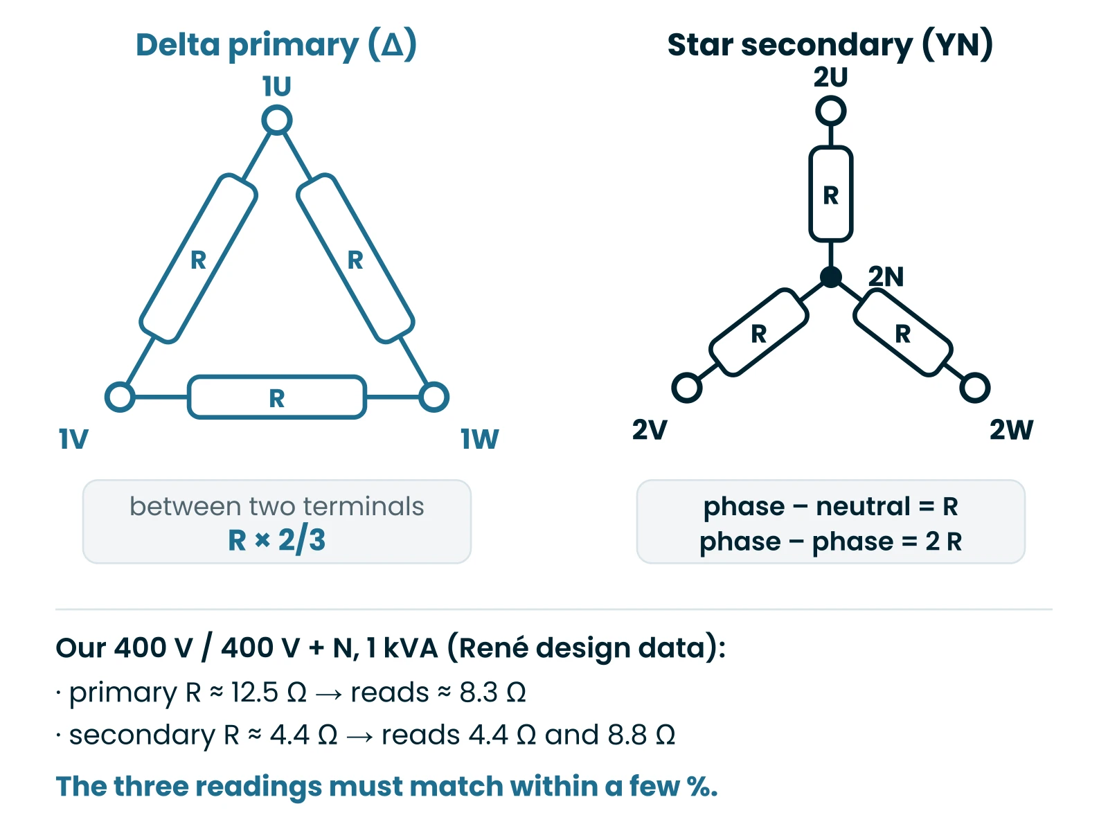
A three-phase transformer carries three identical coils, one per phase. To test a transformer of this kind, the diagnosis becomes a comparison: the three readings must be equal. But what the ohmmeter reads depends on the connection.
- In delta: between two terminals, you measure one coil in parallel with the other two in series, which is two thirds of its resistance.
- In star with neutral: between a phase and neutral you read one coil; between two phases, two coils in series.

A reading clearly different from the other two points to the faulty coil: that is how to test a transformer with three phases in a few minutes. With the power on, the logic is the same: three equal phase-to-phase voltages, three equal phase-to-neutral voltages. Our models are in the three-phase transformers category.

Repair or replace: how to decide
A transformer does not wear out: it has no bearings and no contacts. When it fails, it has almost always run too hot, through overload, poor ventilation or a short circuit downstream. Before fitting a new one, find that cause, or the next one will suffer the same fate. That is what knowing how to test a transformer is really for: finding the real culprit.
| Test result | Decision |
|---|---|
| Everything is normal | The transformer is sound: the fault is downstream. |
| Wire broken at a visible exit | Repairable by a professional, if it can be resoldered without strain. |
| Winding open inside | Replace. |
| Insulation fault | Replace, without powering it again. |
| Heats off load, low voltage | Replace: shorted turns. |
| Large three-phase unit or model no longer made | Ask for a quote for an identical build. |
On a small transformer, rewinding almost always costs more than a new unit. For a model that no longer exists, we build it from its plate and dimensions as a custom transformer; the free quote form is enough to get started.
Reading the plate to order the right replacement
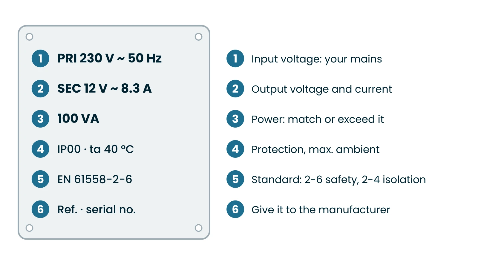
Once you know how to test a transformer, all that remains is to replace it, and testing a transformer often ends with an order. Everything you need is on its plate: photograph it before removing the unit, as heat sometimes fades it.

- Voltages: primary and secondary, to be matched exactly. An old “220 V” or “240 V” unit is replaced by a 230 V one.
- Power: in VA, to be matched or exceeded. If the power is unreadable, work it out: output current × output voltage.
- Standard: EN 61558-2-6 for a safety transformer, the kind used for pools and damp locations; EN 61558-2-4 for an isolation transformer.
- Dimensions and fixing: measure the distance between the fixing holes, especially in a tight enclosure; our page on IP and IK protection ratings helps you choose the enclosure.
The most requested models are grouped on two pages: 230 V to 24 V transformers and the 12 V page mentioned above. The full range is under single-phase transformers.
The most common replacements, in 12 V and 24 V
230V to 24V Transformer – Single-Phase Linear
Swimming Pool Transformer – Lighting – 230V -> 12V
Toroidal Transformer – 230V -> 24V
Single-phase Transformer 220V -> 12V
Frequently asked questions
Can you test a transformer without removing it?
Yes for the voltage checks: you measure at the terminals, in place. For resistance and insulation, disconnect at least one wire from each winding; otherwise the multimeter also measures whatever is connected, and the reading means nothing.
Which range should I select on the multimeter?
Ohms (Ω) on the lowest range for continuity, the highest range (MΩ) for insulation, AC volts (V~ or VAC) for a conventional transformer. The DC volts range (V⎓) is only for the output of a power supply.
Can a wound transformer replace an electronic one?
For 12 V halogen lamps, yes, provided its power covers the lamps: it gives them 12 V AC at 50 Hz. For LED lamps, first check that they accept AC; if not, they need a DC power supply.
Do I need an electrician for testing a transformer?
No. Testing a transformer with the power off is within reach of a careful householder. As soon as you have to open a consumer unit, work near live 230 V terminals or enter a plant room, call a qualified electrician.
Your diagnosis in five steps
Here is how to test a transformer in ten minutes, safely and without blaming the wrong part: keep to this order. It works for a gate transformer as well as for a pool light.
- Switch off, disconnect, check that no voltage is present.
- Measure the continuity of the primary and the secondary.
- Check the insulation between windings and to frame.
- Reconnect, measure the no-load voltage, then on load.
- Compare with the plate: 3 to 6% above off load is healthy.
If testing a transformer points to the transformer itself, note its plate and dimensions: the replacement takes a few minutes to choose, and we build an identical unit when the original no longer exists.
Read next
Guides8 min read
Isolation transformer for boilers: the complete guide
An isolation transformer for boilers gives the boiler a clean neutral and, with its tappings, brings a high supply back to about 230 V. How it works, which VA rating to choose, how to wire…
Read the article
Documentation5 min read
Earthing System (TNC, TNS, IT): The Key Role of the Isolation Transformer
An isolation transformer can change your earthing system thanks to its winding connection: It can create the neutral. Discover our guide,

Read the article
Tutorials2 min read
How to power a caravan with 12V?
A 12V power supply for a caravan or motorhome must be provided by a 12VDC DC power supply. In this article you'll find more details on how to power your vehicle from the mains.
Read the article
Design office
A question about your installation?
Tell us about your supply and your equipment: we’ll recommend the right transformer, standard or custom-made, and reply within 48 hours.
+33 4 66 80 14 33Monday to Friday, 8 am – 6 pm (French time)